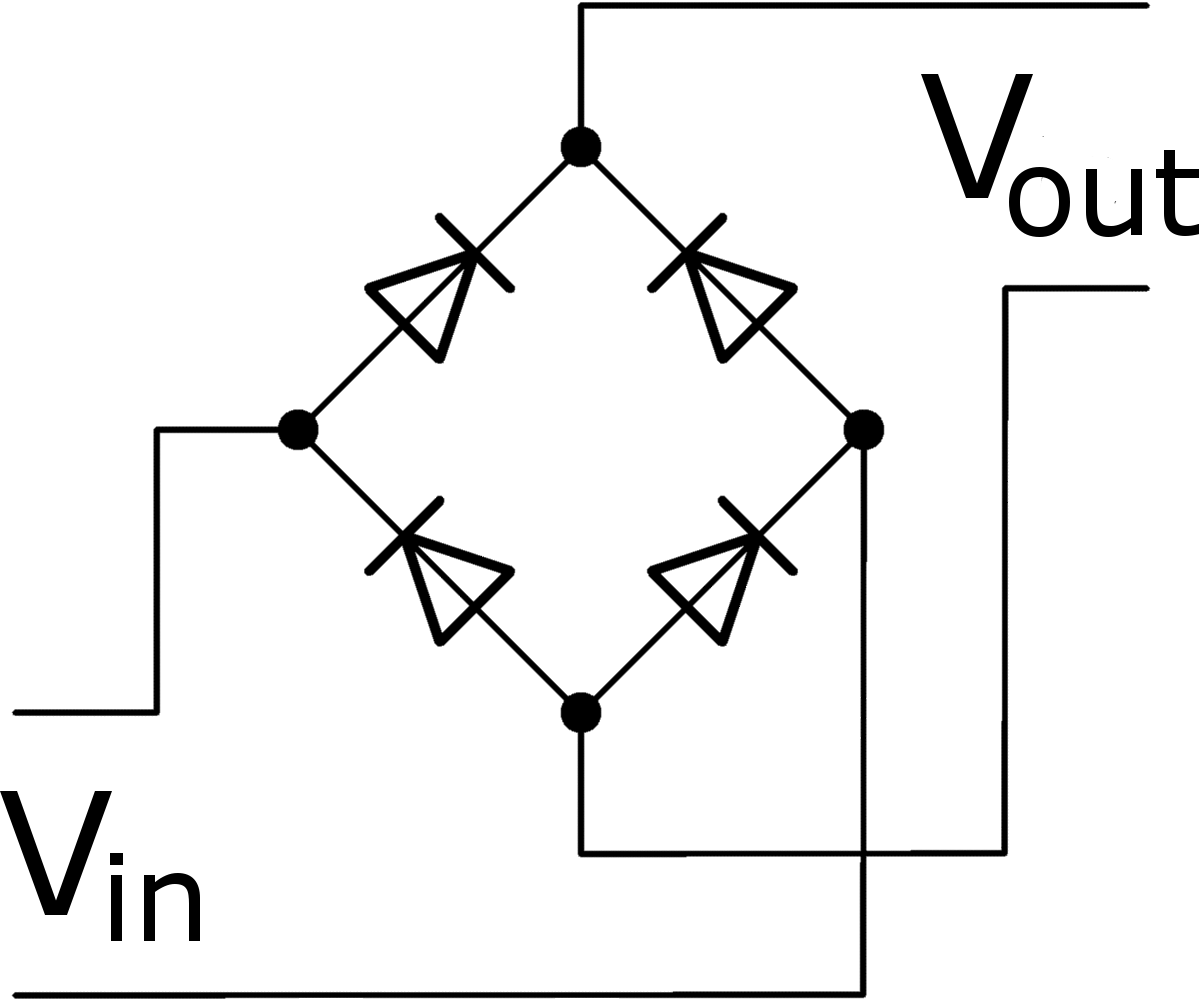
Bridge Rectifier Circuit Diagram Explained Bridge Rectifier
What is bridge rectifier? working, circuit diagram & waveforms Full wave bridge rectifier circuit diagram diagrams working principle Rectifier bridge application circuit basics applications diagram output waveform circuits diodes used diode dc power voltage transformer advantages peak high
Bridge Rectifier Circuit Diagram Ppt
Diode bridge rectifier Simple bridge rectifier circuit Bridge rectifier
Bridge rectifier circuit, construction, working, and types
Bridge rectifier consists of diodes with very less piv and no centerBridge rectifier circuit diagram explained Bridge rectifier : circuit diagram, types, working & its applicationsBridge rectifier – construction, working, advantages.
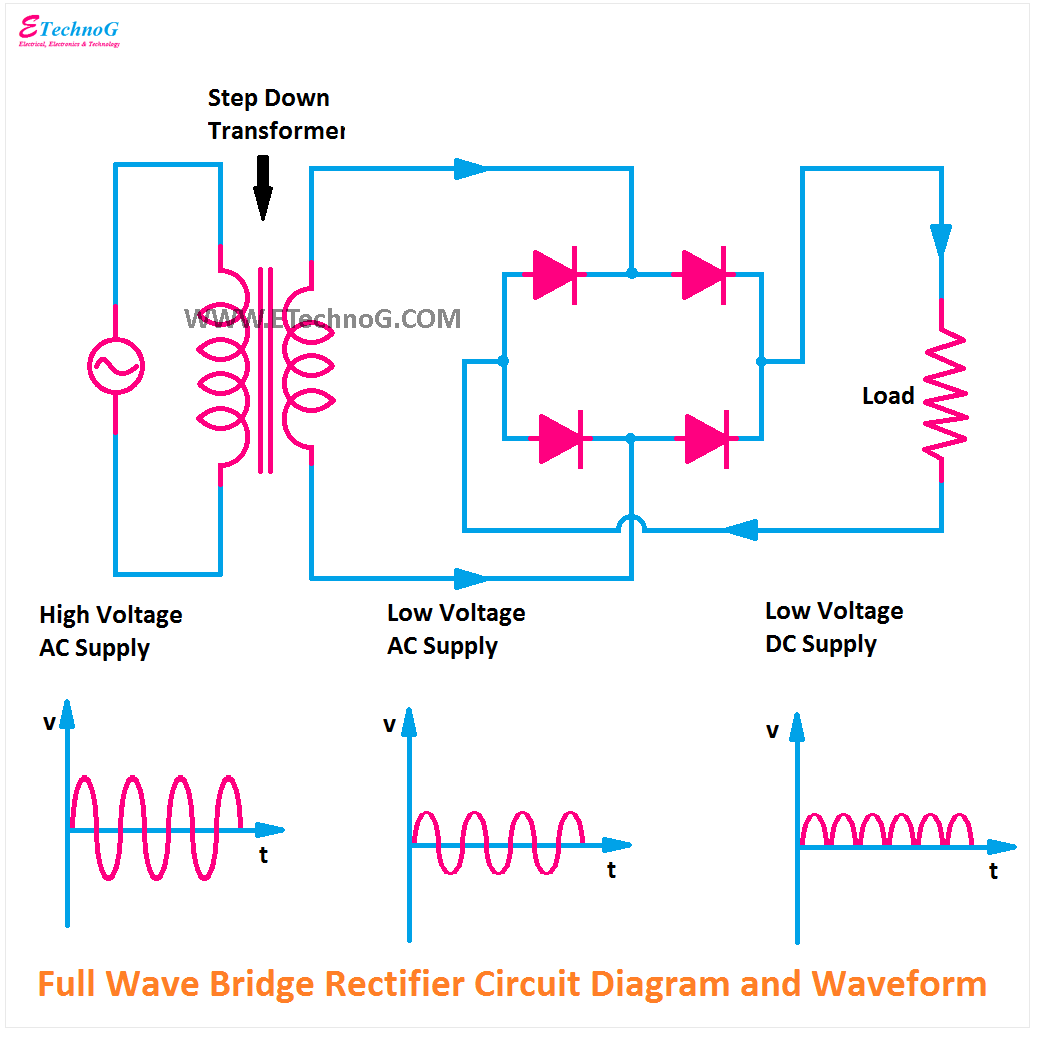
Full wave bridge rectifier circuit diagramThe full-wave bridge rectifier Full bridge rectifier circuit diagram13+ bridge rectifier schematic.

Full wave bridge rectifier download scientific diagram
Rectifier bridge circuit application applications basics diagram output waveform circuits diodes diode used dc voltage power transformer elprocus functions advantagesBridge rectifier functionality Rectifier bridge10 rectifier circuit diagram robhosking diagram.
Rectifier circuit circuitsRectifier electrosome Construction and working of bridge rectifier presentation[diagram] 24v rectifier wiring diagram.

Bridge rectifier circuit diagram explained
Full wave bridge rectifier copy of full wave bridge rectifierBridge rectifier calculator Bridge rectifier circuit, construction, working, and typesControlled rectifier definition, classification, applications theory.
Half wave bridge rectifier circuit diagramFull wave bridge rectifier schematic Full wave bridge rectifier circuit diagramRectifier diode transformer diodes advantages wave elprocus waveform consists regulator functionality regulated.

Bridge rectifier circuit diagram ppt
Full bridge circuit diagramDiode bridge rectifier electrical4u Why is zener diode not used in rectifier circuits?.
.


Bridge Rectifier Circuit Diagram Explained

Controlled Rectifier Definition, Classification, Applications Theory

Bridge Rectifier - Electronics Reference

Half Wave Bridge Rectifier Circuit Diagram

Why is Zener Diode not used in rectifier Circuits?

Full Bridge Circuit Diagram
![[DIAGRAM] 24v Rectifier Wiring Diagram - MYDIAGRAM.ONLINE](https://i2.wp.com/theorycircuit.com/wp-content/uploads/2018/03/full-wave-bridge-rectifier-circuit-diagram.png)
[DIAGRAM] 24v Rectifier Wiring Diagram - MYDIAGRAM.ONLINE

Full Wave Bridge Rectifier Copy Of Full Wave Bridge Rectifier - Riset